|
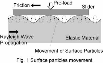
| Fig 1. Surface particles movement |
| When the Rayleigh wave propagates on elastic material surface, particles on the surface move along an elliptical locus as shown in Fig. 1. A slider arranged on the elastic substrate is driven by frictional force. The slider is pre-loaded so that friction force is enough to drive. |
|
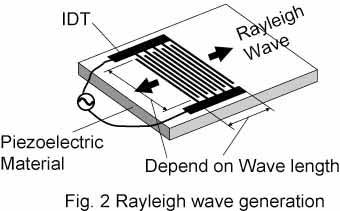
| A piezoelectric material of 128o Y-cut LiNbO3 was used for the SAW motor. When high frequency voltage is input to an interdigital transducer (IDT) on the piezoelectric substrate, the Rayleigh wave is generated and propagates, as shown in Fig. 2. |
|
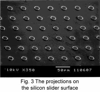
| The slider made of silicon has many projections on its surface in order to control contact conditions. Figure 3 is a photograph of the slider surface. The diameter of the projections is 10 to 50 µm. |
|
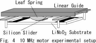
| The size of the transducer was 15 x 60 x 1 mm3. The operating frequency was 9.6 MHz. The dimension of the silicon slider was 4 x 4 x 0.3 mm3. Figure 4 shows experimental setup of the 10 MHz linear motor. The slider was pre-loaded by leaf spring and the pre-load was about 30 N. |
|
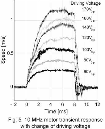
| Figure 5 shows the transient response of the 10 MHz SAW linear motor. When the driving voltage was 170 V0-p, the 10 MHz motor worked at more than 1.1 m/s. The maximum output force was 3.5. The response was more than 130 kHz. |
|
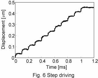
| We also succeeded in the step driving. 80 V0-p 30 cycle of the operating frequency was driven to the IDT. The slider motion was observed by using the laser Doppler displacement meter. 40 nm steps can be seen in Fig. 6. |
|
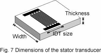
| Limits of the stator transducer dimensions such as the width and the thickness described in Fig. 7 are proportional to wavelength of the SAW. Therefore, the transducer can be miniaturized by using higher operating frequency. If we use 5 times higher frequency, the limits of the width and the thickness are a fifth. In the case of 50 MHz operation frequency, the limits of the width and the thickness of the stator transducer are 3 mm and 0.2 mm approximately. A problem may occur with miniaturizing the SAW motor. When tangential vibrating velocity is 1 m/s, vibration amplitude is about 20 nm at 10 MHz operating frequency. By using 5 times higher frequency, the amplitude becomes a fifth, 4 nm. However, surface-roughness of the stator transducer is (Ra =) 5 nm and is same as the vibration amplitude. It is wondered that the miniaturized SAW motor can actually work. |
|
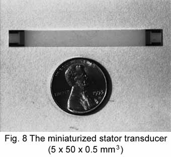
| Figure 8 is a photograph of the miniaturized stator transducer which was fabricated on trial. The size of the transducer was 5 x 50 x 0.5 mm3. The volume became a seventh of the previous one. Resonance frequency of the IDT, the operating frequency, was 49.76 MHz. |
|
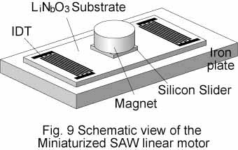
| Figure 9 shows the schematic view of the miniaturized SAW linear motor. The stator transducer was arranged on a iron plate. Dimension of the silicon slider was 2 x 2 x 0.3 mm3. The diameter of the projections was 20 mm. A magnet whose dimension was 4 x 4 x 3 mm3 was arranged on the silicon slider. |
|
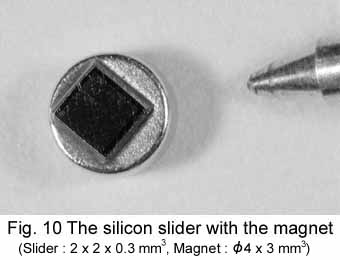
| Figure 10 is a photograph of the silicon slider combined with the magnet. The slider total weight was 0.18 g. The pre-load, magnetic force added to the gravity force, was 0.13 N. |
|
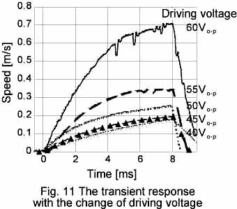
| The miniaturized SAW linear motor was driven for 8 msec. Driving voltage was varied from 40 to 60 V0-p. The slider motion was observed by using a laser Doppler displacement meter. Figure 11 shows the transient response with the change of driving voltage. The maximum traverse speed of 0.7 m/s was obtained when the driving voltage was 60 V0-p. This is 70 % of the tangential vibration velocity. The maximum acceleration of 200 m/s2 was observed from the figure. The maximum output force of 0.036 N was calculated from the acceleration and the slider weight. This force was 28 % of the pre-load. The 50 MHz motor has no guide. It seems that the increase of the ratio is due to the linear guide. |
|